AC/DC Power
Distribution panel: DC distribution module
In the distribution panel, the DC distribution module is one of the most important components. This is because it allows the energization of various loads, thereby serving the purpose of protection and control of DC energy.
Method of protection for DC loads
Just like with AC electricity, a method of distributing DC electrical energy generated by the power distribution panel is also necessary, thus forming distribution circuits.
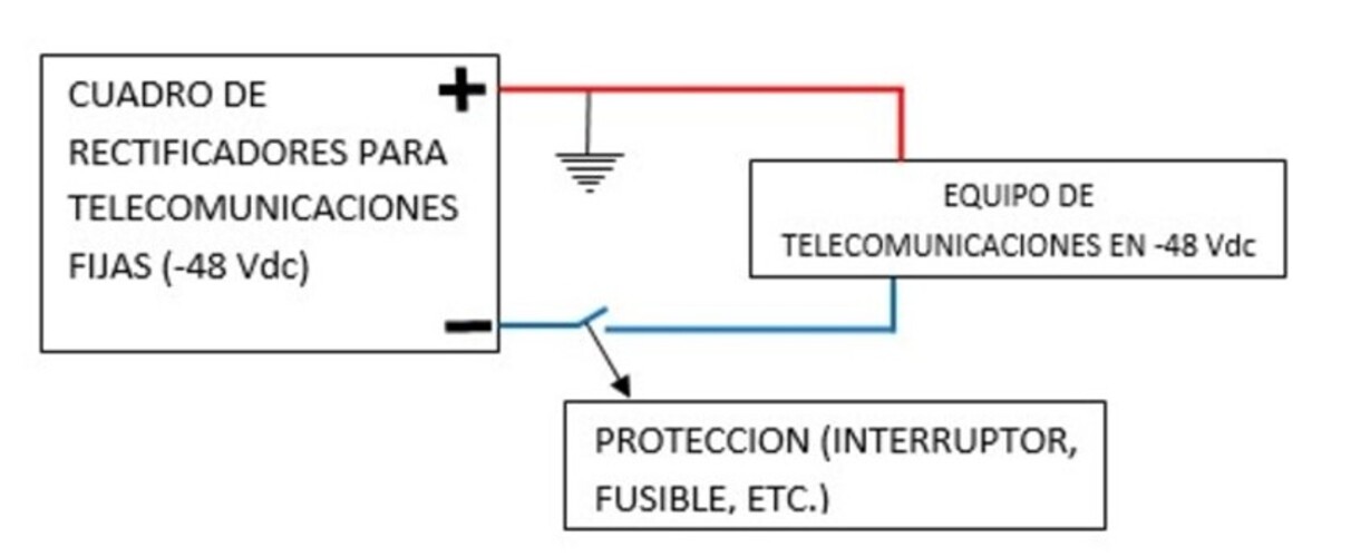
It’s crucial to note that protections are placed on the active pole, specifically the one that is not connected to ground.
For instance, in the case of fixed-line telephony systems or -48Vdc, the protection is placed on the negative pole, as illustrated in the following diagram.

Additionally, if the loads are located near the rectifier equipment, let’s say about 20 meters away, they are directly powered from the available points.
However, if these loads are far from the rectifier equipment, they are energized using remote DC distributors. This would be done in a manner similar to how it’s done with AC distribution panels.
This approach is taken because voltage drop is critical in DC systems, which leads to the need for larger wire gauges. This is due to the fact that in this system, there is low voltage but very high current.
The choice of distribution mode depends on the designer and the maximum wire gauge that the terminals can support. Both for the rectifier protection and the equipment to be powered.
We’ve described the above along with the equipment in our post titled PDB: remote DC distribution. Stay tuned for it!
Now, it’s worth noting that typically the DC Distribution Module comes in two versions:
- DC Distribution Panel, which only has protections for telecommunications loads.
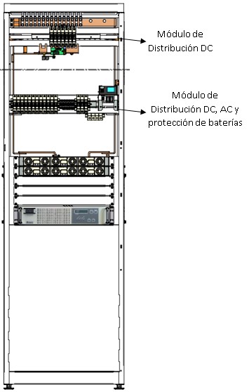
- Multifunctional Distribution Panel, which integrates the DC Module, AC Module, and Battery Protection Module.
In the image provided below, you can see the positions of each module in a typical switchgear panel.

DC distribution panel

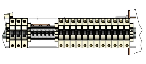
The DC Distribution Panel contains only protections, typically in the form of single-pole circuit breakers, for the telecommunications loads to be powered.
This is done so that in case a circuit breaker trips, it can be quickly reset. The priority is to minimize the downtime of the telecommunications service.
This device has a specific number of slots to accommodate circuit breakers based on their capacity. The maximum conductor size that can be connected depends on this capacity.
For instance, some panels have the capacity for 20 circuit breakers of up to 20 Amps. Allowing for a maximum conductor size of 13.29 mm² in cross-section.
The presence of this DC Distribution Panel module in the power distribution panel depends on the number of loads to be connected.
It’s important to note that multiple DC Distribution Modules can be installed in a single power distribution panel. The quantity and capacity in Amps of each module depend on the manufacturer’s specifications.
The determination of protection capacity depends on equipment consumption. We’ll teach you the calculation method in our Telecommunication power systems design course. Click here to learn about its content.
We will continue with this topic in our next article titled Main module of the power distribution panel. Don’t miss it!
Do you like our content?
If you liked this article, leave us your comment, and if not, then let us know how you would like us to improve it.
Also, we invite you to read the contents we have published for you on our website energydcac, they will surely be very interesting for you.
Image sources
- energydcac.com
- cantv.com.ve

