
AC/DC Power
AC-DC Rectifier for Telecommunications. Part 2
Ago
We continue with the topic on AC-DC rectifier for telecommunications. Here, I will provide further details on the most notable characteristics of this equipment.
To enhance your understanding of this subject, I encourage you to read the post AC-DC Rectifier for Telecommunications. Part 1.
Likewise, I recommend reading all the articles on our blog energydcac. These articles contain relevant information on everything related to DC power systems for telecommunications, as well as information about solar energy.
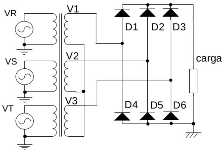
Connection Method of AC-DC Rectifier in Telecommunications
DC power systems for telecommunications have a minimum of 2 rectifiers. This is because it is anticipated that one of them might experience a failure.
In our Course on Designing Power Systems for Telecommunications, you will learn how to calculate the quantity, capacity, and other parameters of these devices.
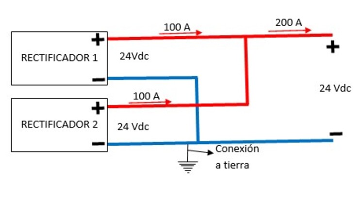
The connection method of AC-DC rectifier for telecommunications is in parallel with each other and with the load. As a result, the total voltage across their terminals remains constant while the current adds up.
For instance, if two rectifier units with a voltage of 24 V are connected. With their negative poles grounded to 0 volts and a total power capacity of 2400 W (each drawing 100 Amperes).
Being in parallel would maintain the voltage across their terminals at 24 V, and the total current would be 200 Amperes. You can better understand this with the following illustration.
It is important to note as a basic concept that the current is determined by the load. This applies to both DC and AC electricity.
What we mean to convey by this is that even if you have a rectifier system with a capacity of 1000 Amperes. If the load only requires 10 Amperes, then the system will only provide those 10 Amperes.
For voltage, the situation is the opposite, if you have a rectifier system for 48 Vdc and you connect a load designed for 24 Vdc. It’s highly likely that the load would be damaged due to overvoltage.
The above holds true if the load doesn’t have overvoltage protection, but that’s a topic we will delve into in a future post.
As an interesting fact: What happens if one of the rectifiers has a higher voltage than the rest?
If one of the rectifiers has a higher voltage level than the others, it will assume as much load as possible.
For example, if you have a 48 Vdc system composed of 4 rectifiers, each rated at 100 A, with a load consumption of 250 A. And one of the rectifiers is operating at 48.1 Vdc.
The rectifier with the higher voltage will assume 100 Ampere of load, while the remaining 150 A will be divided among the other 3 rectifiers.
The reverse scenario occurs when one of the rectifiers has a lower voltage than the rest. Following the previous example, if one of the rectifiers is connected at, let’s say, 47.9 Vdc. It will not operate since the other 3 rectifiers will share the load of 250 A.
An observer would notice that the indicators for this rectifier show a contribution of 0 Amps.
This rectifier will only start operating when the others are working at maximum capacity, i.e., when the load consumption exceeds 300 Ampere.
However, in a properly designed system, the load value will never reach the maximum capacity of the rectifiers, as there is a reserve percentage.
You will understand this better and we will clarify it in our Course on the Design of DC Power Systems for Telecommunications. Check out its contents Here.
In the upcoming post, titled Electrical energy in telecommunications, we will delve into these devices.
If you enjoyed this article, let us know in the comments. Also, if you have any questions, don’t hesitate to contact us. We are always available to assist you.
Image Sources
- energydcac.com
- researchgate.net