AC/DC Power
Controlled and uncontrolled AC-DC rectifiers
Dic
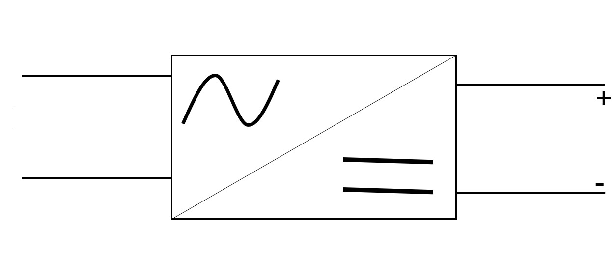
AC-DC rectifiers are widely used in power systems for telecommunications, converting AC energy into DC. In this post titled Controlled and uncontrolled ac-dc rectifiers, we will explore the two types of conversion.
This conversion, technically termed wave rectification, involves eliminating the alternation in the alternating current signal and delivering a linear signal of constant value. Hence, it is also known as Full wave rectification.
As you may infer, the rectifier serves as the heart of energy for telecommunications, given that the majority of equipment operates on DC electricity.
Uncontrolled rectification
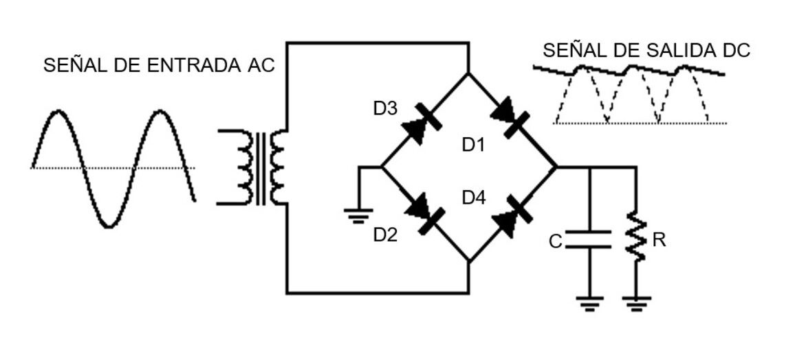
In this type of rectification, the equipment produces a wave with fixed values, either in current or voltage. It employs diode bridge technology, which has the advantage of being cost-effective and straightforward.
In addition to its applications in power systems for telecommunications. It is also utilized in motor controllers, AC servomechanisms, switched-mode power supplies, and other power electronics applications
Controlled rectification
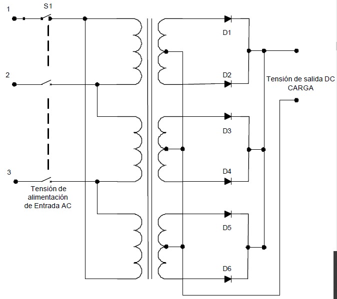
This process is more elaborate than the previous one, and the waveform undergoes additional transformations as converters controlled by thyristors are used.
Nowadays, these components have been highly developed, capable of handling high voltages and currents. Therefore, they are employed in high-power three-phase rectifiers.
To make this concept clearer, three-phase rectifiers can be defined as the combination of three single-phase AC-DC rectifiers.
These components are increasingly used in telecommunications due to energy-saving benefits. Remember, higher voltage means lower current, reducing energy losses.
Going into more detail, these current converters can be either single-phase or three-phase, depending on the power source.
They are further classified as:
- Semiconverters, characterized by having the same polarity of current and voltage at their output
- Full converter, where the output current has a single polarity, and the voltage can be positive or negative according to equipment specifications
- Dual converter, the most versatile and widely used, allowing both positive and negative polarity for the output voltage and current, with adjustable magnitudes
Needless to say, this last form of control is the most commonly used in AC-DC rectifiers.
Furthermore, both controlled and uncontrolled rectification technologies are currently employed based on the application and equipment cost.
In both cases, it is essential to install filters at the output of the equipment to ensure the rectifier delivers a purer signal without electrical aberrations.
Concluding…
Up to this point, we conclude this post, which we hope has been enjoyable and highly useful for you. At energydcac, you’ll find a wealth of content on this topic that we are confident you’ll appreciate. Be sure to check them out!
In our post AC-DC rectifiers with thyristor regulation (Rectificadores AC – DC de regulación a tiristores) we explain the different technologies of these devices.
Up to this point in the post, we hope it has been to your liking and very useful. At energydcac, you will find a lot of content on this topic that we are confident you will enjoy. Be sure to check them out!
If you wish to delve deeper into this world, we recommend the Telecommunications and Critical Systems Power System Design Course. Look through all its content to convince yourself that it’s the right fit for you. Don’t miss out on this opportunity!