
AC/DC Power
DC power distribution panel: The Main Module
Ago
We continue with the series about the DC power distribution panel and its components, completing here the post Energy distribution panel: the DC distribution module . Which we invite you to read along with the rest of our engaging content published on energydcac.
As you are already aware, the power distribution panel is the component that serves as the DC energy source for the telecommunications equipment. In other words, if it doesn’t function, then the entire service comes to a halt.
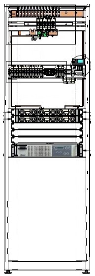
Before we delve into the description of this energy distribution panel, we’re showing you an image of a DC power distribution panel with its panels. However, we’d like to clarify that the appearance may vary depending on the manufacturer.
Why is this panel called the main module?
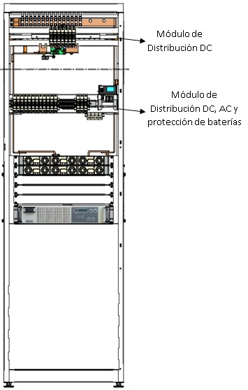
This designation is due to the fact that this electrical distribution module contains the following:
- DC Distribution Panel, where the electrical output protections are placed to supply power to equipment
- AC Protection Panel, which is the point where the AC power conductors arrive and from where the Rectifier Panel is supplied
- Battery Panel, which contains the DC electrical protections for backup batteries
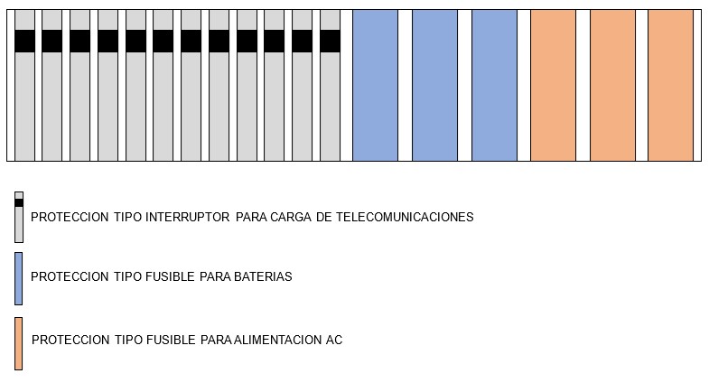
Although the type of protection depends on the manufacturer. They are generally of the circuit breaker type for load connections and fuse type for AC power and batteries.
This main module is divided into sections with clearly defined positions for electrical protections. Here is a schematic of a typical module for your reference.
As you can observe, the DC distribution part and battery protections are situated adjacent to each other. This is due to the fact that they share the negative pole bar in the case of fixed telecommunications energy systems.
In the scenario of mobile telephony systems, this main panel corresponds to the positive pole.
It’s worth highlighting that, contingent upon the design of the power panel, this module possesses a specific capacity in amperes and positions for electrical protections. For this information, you should refer to its technical specifications.
Each power panel must have at least one main module. And if you want to expand the number of available electrical protections, high-quality equipment allows you to do so by installing additional DC distribution panels.
Almost always, the maximum wire gauge that can be connected is 13.29 mm² in cross-sectional area. However, you can ascertain this with precision by consulting the equipment manual.
And if the conductor is of a larger gauge than recommended by the manufacturer?
If you need to connect larger gauge conductors, consult our Course on Sizing and Design of DC Power Systems for Telecommunications and Critical Systems.
In it, we present the different solutions you can take and recommend the best ones. Make it yours now!
One thing we can tell you in advance is that you should never remove strands from the conductor to make the connection.
Where is the non-active or ground conductor of DC connected?
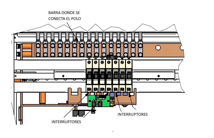
This refers to the positive or negative pole in DC power systems for fixed and mobile telecommunications, respectively. In this case, the conductor is connected directly to the corresponding busbar without any type of protection.
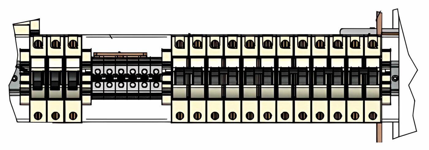
Usually, the busbar is integrated with the protection module, as shown in the image above. This busbar is connected to the main busbar of the distribution panel.
However, other manufacturers place a single busbar for making these connections. In such cases, reputable brands include all the necessary elements for its expansion. You can verify this by asking the seller.
For high-quality distribution panels, this connection is made through a copper busbar. Its dimensions are calculated based on the maximum number of distribution panels the equipment can support and its capacity.
In the diagram shown below, you can see this busbar. In well-constructed distribution panels, it usually has two holes for connecting each load. This is done using double-hole terminals to prevent the conductor from loosening.
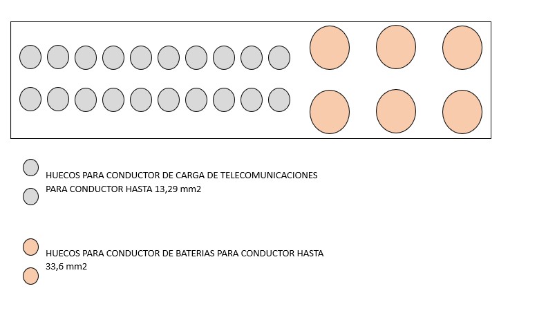
As you can see, the holes where the positive pole cables of the loads and batteries are connected have different sizes due to the supported conductor gauge.
We will discuss these gauges in our article What are wire and conductor gauges?.
Keep in mind that this busbar also appears in the case of the load protection panel. Therefore, we invite you to read our published post Distribution Panel: The DC Distribution Module.
Note that the larger diameter holes are typically for connecting the conductor of battery banks.
We conclude here…
In the Design of Power Systems for Telecommunications course, we explain the calculation methods for selecting protections and wiring for DC power supply to telecommunications equipment.
Furthermore, we delve into this and other topics. Don’t miss out on taking the course! If you want to know more about its content, simply click here.
If you have any questions about this topic or any other subjects we’ve covered in our content, feel free to reach out to us. At energydcac, we also offer other content related to DC/AC power systems that you’ll find highly interesting. Visit us and explore!
Image source
- energydcac.com
- cuadriserca.es
- siemens.com