
In our article AC – DC rectifier: current and voltage alarms and settings, we explain how it protects against abnormal current and voltage conditions. Now, let’s explore other alarms it has and their key settings in energy systems for telecommunications.
Most of these warnings are indicated by the Control and Alarm Module of the Power Panel, both locally and remotely. Additionally, the AC – DC rectifier for telecommunications also has its own signaling.
It is essential to adjust them correctly, test them, and measure them to avoid future problems.
You should be aware that the variables we are about to show you are common in good-quality equipment. Therefore, make sure that the AC – DC rectifier for telecommunications you plan to acquire for your projects has these properties. Let’s take a look!
High ripple factor alarm
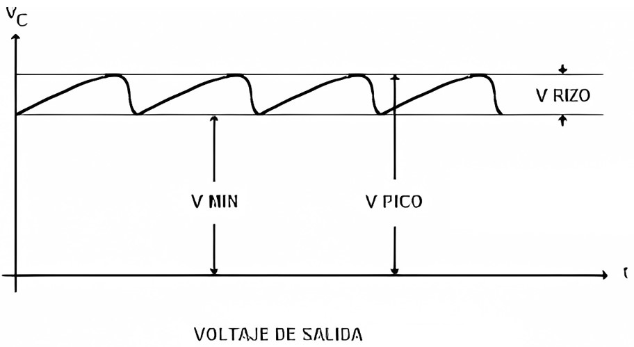
This alarm occurs when the equipment detects an output DC waveform with a ripple that exceeds 5% of the AC input. This condition causes the AC-DC rectifier to disconnect, as it can lead to damage to the loads.
Alarm for loss of one input phase
The alarm activates when one of the AC supply phases is lost, in both three-phase and two-phase rectifiers. It acts by reducing the output current to protect the circuit containing the filtering capacitors.
The battery bank will contribute the surplus current that the rectifier cannot supply if the other rectifiers cannot do so.
Charger failure alarm
The same is activated when the rectifiers are recharging the battery bank in the telecommunications power system. It occurs when they are operating in float voltage.
It happens when sensors detect an abnormal condition in the batteries. Which could be a short circuit in any of the cells or an open circuit.
General AC – DC rectifier failure alarm
This is a signal that activates along with any of the AC – DC rectifier alarms. It lights up whether the equipment disconnects or not.
When addressing a fault in the system, this alarm should be inactive. Otherwise, some fault condition persists.
Setting for parallel operation
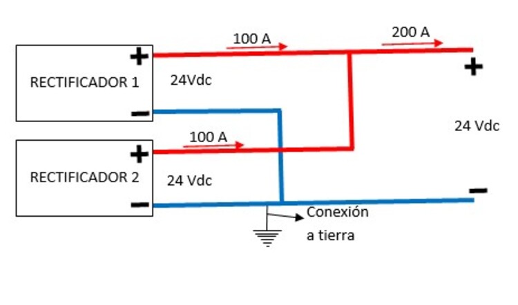
This is a setting done through the Control Module. Some power panels also automatically integrate a new AC-DC rectifier in parallel with the existing equipment.
In any case, they must have the same characteristics, such as regulation technology and output capacity.
Adjustment for partial load operation
This setting is crucial to protect the integrity of the rectifiers. It anticipates a situation where, at some point, the AC input power is reduced to a level lower than what the rectifiers require.
In this case, the output power of the rectifier AC-DC is adjusted to approximately 50% of its total capacity. The missing power will be supplied by the battery bank.
Remote stop adjustment
This option is used when it is necessary to turn off an AC-DC rectifier from an external location, either due to faults or simply as part of an energy-saving program.
For more details on the operation of AC-DC rectifiers, be sure to visit energydcac.
Also, we invite you to read our upcoming article Selecting the AC/DC Telecom rectifier: factors to consider. You’ll learn about the variables of AC-DC rectifiers for telecommunications that you should consider for your design. Don’t miss it!
And don’t forget that we have the Sizing and Design Course for DC Power Systems for Telecommunications just for you. With it, you’ll learn everything you need for your project. Check out its content here.