AC/DC Power
Electrical cables and conductors: resistivity and electrical resistance
Electrical resistance is one of the most important parameters you should know about cables and conductors because its value will determine whether equipment operates correctly.
We invite you to read our post. Next, we will explain how to determine these parameters. Let’s get started!
Resistivity and electrical resistance in conductors
The resistivity in metallic conductors is a physical property that indicates a material’s capacity for conducting electrical current.
It is represented by ‘ρ’ (rho) and is measured in ohms per meter (Ω·m). Resistivity is influenced by the material’s composition, temperature, and crystalline structure, determining its electrical conductivity.
This is one of the factors that determines the resistance of a conductor. Which we can understand as the opposition experienced by electrons as they move through a conductor. Creating difficulty for current to flow in a closed circuit.
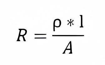
The way to calculate this resistance from resistivity is as follows:

Where:
ρ = Resistivity of the material, which is 1.7 x 10^-8 ohms per meter (Ω·m) for copper, And 2.65 x 10⁻⁸ ohms per meter (Ω·m) for aluminum. These factors are taken at a temperature of 20°C.
l = Length of the conductor in meters. It’s important to consider the distance from the source to the load and from the load to the source. In other words, this length can be taken as 2l if the conductor is the same for both cases.
A = Cross-sectional area of the conductor. To calculate it, you need to pay attention to the shape of the conductor because the area is calculated based on its geometry. You should express it in square meters (m²).
Here are the equations to determine the areas of common conductor surfaces based on their geometry:
If the area is square or rectangular:

You should express each side in meters.
If the conductor is cylindrical:

Knowing that:
Π = 3.1416, approximately
r = Radius of the conductor in meters
How does ambient temperature affect electrical resistance?
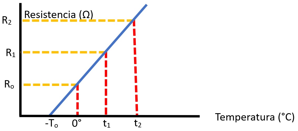
Experimental evidence has shown that as the external temperature increases, their resistance increases linearly. You can observe this in the following graph:

This resistance is expressed in Ohms per unit length, and there are tables that express these values according to the gauge. Usually shown as Ω/km (Ohms per kilometer).
We will be discussing the above in our post What are gauges in electrical conductors (Qué son galgas en conductores eléctricos). Don’t miss it!
This increase can be calculated using the following equation:

Where:
R = Resistance value you want to find for the conductor
R1 = Resistance value given in the conductor’s specifications, which is provided for a temperature of 20°C and expressed in Ω (Ohms)
t1 = Tnless otherwise stated, this temperature is 20°C
t = The temperature for which you want to find the resistance
α = Called the Thermal Coefficient of Resistance, which depends on the conductor’s material and its temperature. Its values for 20°C are:
- For copper conductor: 0.00393
- For aluminum conductor: 0.00390
The explanation for this trend is that an increase in temperature raises the thermal energy of electrons. Leading to more frequent erratic collisions between charges, resulting in greater dissipated heat.
Was this article helpful to you?
In our upcoming post, Calculation of electrical resistance and its temperature variation in electrical conductors, we will teach you how to apply the equations. To determine these characteristics of a conductor.
Likewise, in the Sizing and design of dc power systems for telecommunications and critical systems course , we will explain to you practically how to use these concepts. Click here to view its content
We also invite you to check out the content we have for you at energydcac, which we’re sure you’ll find very interesting. And if you want to stay updated on our latest news, just register – it’s easy and free.
