
AC/DC Power
Electrical resistance in cables and its variation with temperature
Nov
Knowing how to calculate the electrical resistance in cables, in its various forms, for an electrical conductor is of great importance. This knowledge allows you to determine this parameter even in situations where you may not have access to specific tables or other technical information.
This knowledge can help you quickly diagnose issues with a device’s power supply in case of malfunction.
The electrical resistance of the conductor is a critical factor that significantly impacts the efficiency of electrical power distribution.
In this article, we will also discuss voltage drop in DC systems and provide practical examples of resistance calculations and their real-world applications. Let’s get started!
Calculating electrical resistance from resistivity,
We will assume that there is a circuit with a length of 10 meters, and its cable consists of a copper conductor with a cross-sectional area of 5 mm2.
To begin, we have the following data:
Length (l) = 10 meters
Area or cross-sectional area (A) = 5 mm2 = 4 x 10^-6 m2 or 0.0000004 m2
Resistivity (ρ) of copper = 1.7 x 10⁻⁸ ohms per meter (Ω·m)
The resistance of the conductor will be:
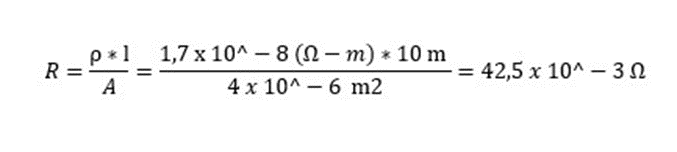
This would be the electrical resistance of the conductor if it is 10 meters in length. However, if you want to know the value per meter, then:
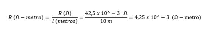
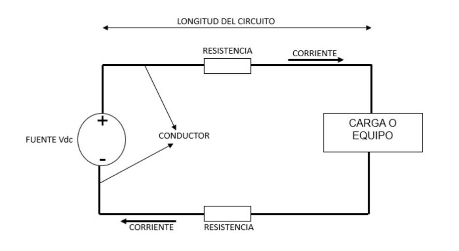
This value corresponds to the conductor from the source to the load, so the load to the source will have the same resistance.
Therefore, the total value will be twice this value, which means that for the 10-meter circuit, the total electrical resistance will be 2 x R, that is, 8.50 x 10⁻³ Ω.
The circuit based on the above can be seen in the image under this subtitle.
Everything mentioned above is for a temperature of 20 °C. Additionally, there are tables that provide resistance data depending on the gauge, cross-sectional area, and conductor length. An example is shown in the following image.
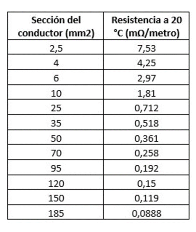
* Data extracted from: alcacompagni.blogspot.com
In our post What are gauges, we talk about these essential elements for the identification and calculation of electrical conductors.
Effect of temperature on the value of electrical resistance
The temperature of the environment surrounding the electrical conductor has a significant influence on resistance. Primarily, as it increases, resistance also increases linearly.
That’s why it’s standardized to provide resistance values for a temperature of 20°C.
Let’s observe this temperature variation assuming the conductor from the previous example is in an environment with a temperature of 50°C.
Before we begin, we recommend reading our article Electrical cables and conductors: resistivity and electrical resistance. This will help you understand the concepts we’ll be using. Don’t forget to check it out!
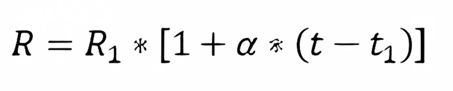
The equation to apply is as follows:
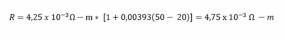
And under these conditions, we have the following data:
Conductor cross-sectional area: 4 mm²
R1 = 4.25 x 10⁻³ Ω – m
α = 0.00393 (for copper)
t = 50 °C
t1 = 20 °C
Calculating:
In our article Calculation of voltage drop in dc electrical conductors, we will continue to study the variables related to conductors.
Likewise, we invite you to read the content we have prepared for you on energydcac. We also recommend that you acquire our Course on sizing and design of dc power systems for telecommunications and critical systems.
You can view its content by clicking here.